In the previous post about the Ping Robot, I created a small hardware platform for the robot recycling an old RC toy car.
For some reasons of simplicity and available electronics I decided to use as controller an Arduino Leonardo and to construct a shield that will contain the ultrasonic sensor and the motors drivers.
So there are two parts which still need to be developed to obtain a ping robot:
- the hardware to mount on top of the robot, corresponding to an Arduino Shield with all the circuit’s components needed to drive both DC motors;
- the software that will be used to read the ping sensor’s signal and to drive the DC motors.
In this post I will describe how to realize the hardware part for the Arduino shield, that it will be mounted on the top of the robot platform.
First problem that I had to solve was the power source, in order to create a small (but completely) autonomous ping robot. So I decided to use a 9V battery to power Arduino Leonardo, ultrasonic sensor and DC motors. I couldn’t use directely 9V on DC motors and ultrasonic sensor, so I had to buy a voltage regulator (L7805CV) that will return a constant 5V power signal from 9V battery.
After I had to decide how to control robot moving using available DC motors. My robot does not have stearing wheels on the front, so when it must turn on one motor and turn off (or invert the rotation of) the other one. It will be drived like a tank! 😀
For simplicity this small robot will turn always on left when it will detect an obstacle, turning off the right side motor. When I was making some test I had to solve the second problem: Arduinos (all models!?) are just microcontrollers, they have to be used only to define the logic of a device; electrical values on pins are just to interact with external world. This is why the TOTAL max output current for ALL pins is 500mA.
So I cannot use directly output voltage/current provided by an Arduino board to turn on DC motors, but I have to use another circuit like a rele to provide the current.
Remembering that I want to maintain the project low cost, I decided to use 2 NPN transistors (2N2222) like switches (a well known practice in DIY projects) like explained here.
I used a 330Ohm resistor between each Arduino output pin and the base pin of each transistor. Moreover, due to the fact that I used NPN transistors, each collector pin must be connected to the motor while the emitter pin is connected to ground for a correct switch circuit.
Finally I created a shield for my Arduino using a prototype breadboard like this one and some male pins soldered on it. I disposed, soldered and connected all components on this PCB, including also the ping (ultrasonic) sensor used for the obstacles detection creation is the HC-SR04 (just few dollars on Ebay) and two SMD LEDs necessary for debug purposes.
Here there are front and rear pictures of the (bad-soldered low-cost DIY-ugly) shield containing all componentes stacked, in a mess of wires and pins 😀


At the end it is possibile to connect the shield to my Arduino Leonardo and test if there is any explosion or short circuit 😀 (seriously I always control all connections to don’t damage Arduino board).
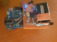
That is a picture reporting the entire “system” (Arduino Leonardo + Shield) and the 9V battery.

Next post will be about Arduino code necessary to control robot movings.
